How Kamoji started, five screens on a bench
Before a single line of firmware was written, we had a decade of building our own smart home and smart office automation at Originally US behind us — custom hardware, our own firmware, none of it off the shelf. Kamoji is where that experience pointed next: an in-car companion that could feel the road and react to it.
The first task wasn't building a prototype. It was picking a screen.
The screen comes first
The display is the single most important electrical component in Kamoji. Every reaction the device has — its personality, its expressions — comes through that screen. Get it wrong at the start and you're rebuilding from the wrong foundation. So on September 26, 2023, before any firmware existed, we ordered five LCD modules spanning different sizes, resolutions and screen technologies.
They arrived two days later.
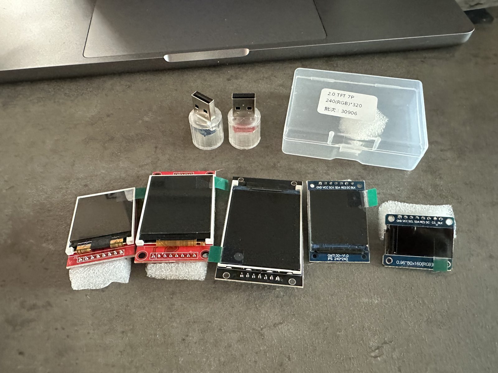
- 0.96" 80×160 RGB IPS — the smallest
- 1.3" IPS 240×240 (GMT130-V1.0)
- 1.44" TFT SPI 128×128 (red PCB)
- 1.8" TFT SPI 128×160 (red PCB)
- 2.0" TFT SPI 240×320 (GMT020-02) — the largest
One by one, each went on a breadboard, got firmware flashed, and was judged on how it rendered.
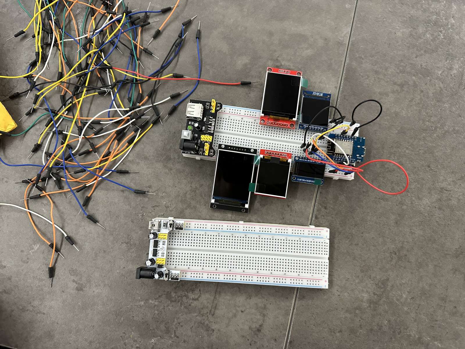
The 1.3" IPS 240×240 (GMT130-V1.0) won — the highest pixel density and the most vibrant color of the five. By 1:33 PM the next day — September 29 — the prototype was already in a car. Not for a proper drive: the IMU was wired in, reading pitch, roll and yaw, and the display sat on the seat showing the live numbers as the rig was tilted by hand. The gyro was being tested in a real car on day one of wiring anything up.
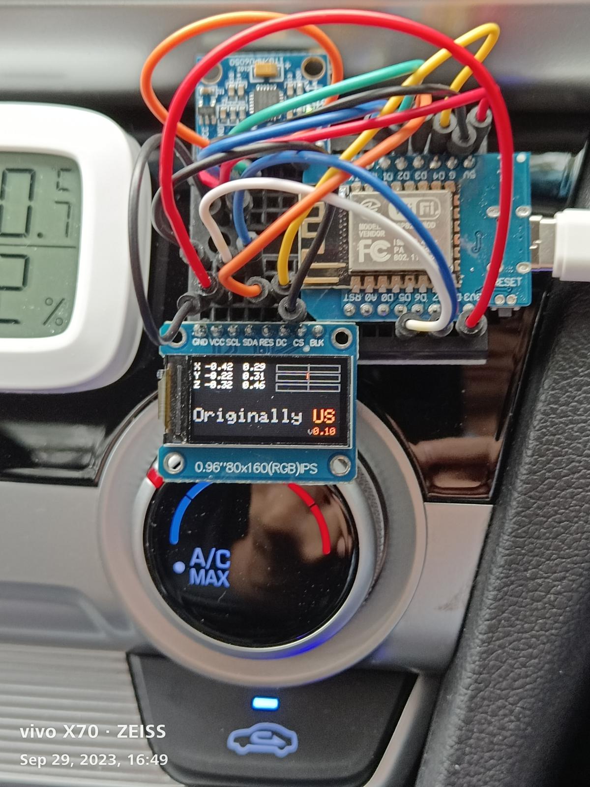
The firmware said "Originally US v0.10". It wasn't Kamoji yet. But the display was chosen, and it was already in a car.
From sensor readings to a driving state machine
October 2 was a full day of firmware work — display iteration, IMU tuning — now that the screen was settled. By October 5 the firmware had grown from raw sensor numbers into a real driving state machine: "Cruising" when the car moved, a braking state when it registered braking, "Stopped" when it stopped. The whole rig — wires hanging off a breadboard, the display held up with nothing, a power bank on a USB cable — was strapped to the center console and taken out on an actual drive, early morning, near Ang Mo Kio.
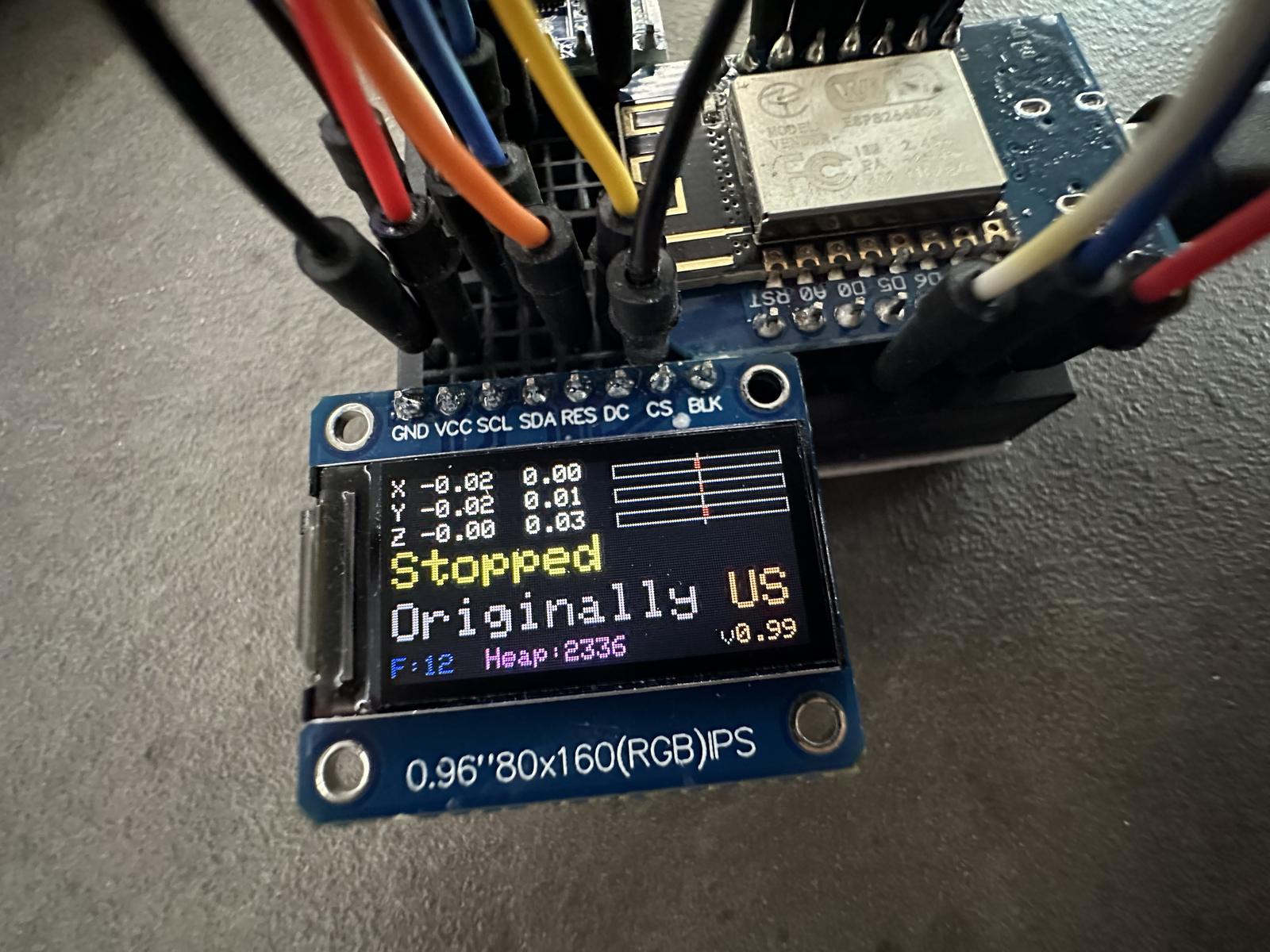
By that evening, the firmware was at v0.99.
What we learned from taking the competition apart
Before and during this early build phase, we did what we always do when sizing up a product space: bought the competition and took it apart. Not reviews, not product pages — we disassembled the closest competing in-car companion devices and character accessories down to the component level, identified the chips, read the PCB layouts, ran their firmware, and tested how they actually responded to inputs.
Most of them contain no sensors at all — they're character displays, not responsive devices. A few claim a motion sensor that barely registers a violent shake. None had OTA firmware updates worth the name, and none showed an architectural commitment to community contribution.
Kamoji samples its IMU 100 times a second and reacts to lean, brake and bump in real time. We hadn't even made full use of that bandwidth yet, and the gap to what was already on the market wasn't close.
The chip that would carry the rest of the project
Two weeks in, on October 14, audio got added and tested — literally plugging full-size headphones into the breadboard rig to check the output. Around the same time we mounted an early rig on a 1/12-scale RC kei truck to test IMU response on a moving platform without needing a real car every time.
That's also when we started looking at the ESP32-S3 as a replacement for the ESP8266 we'd started with — dual core, more memory, Bluetooth, native USB. It's the chip Kamoji still runs on today.
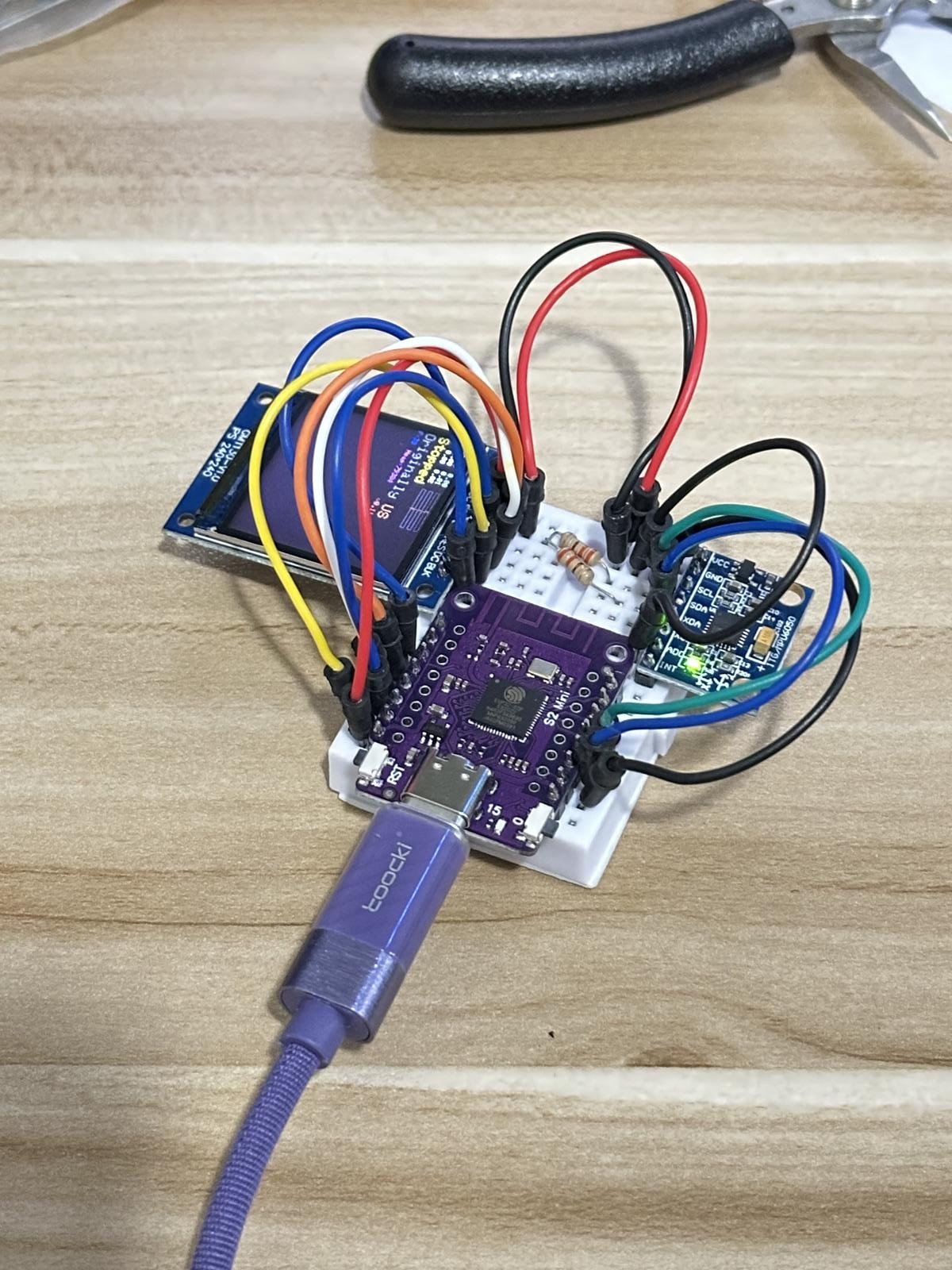
By this point the driving states — Cruising, Stopped, Hard brake — were each triggering their own display output on our own firmware, on our own hardware. Three weeks after five screens arrived on a bench, Kamoji had the beginning of a personality.
This is the first post in a series on how Kamoji got built. Next: the ten PCB revisions it took to get to a board we could ship, and why we designed it to be open hardware.